Welcome to my personal webpage. | home
Robotics | Mirocontrollers | Electronics | My Resume | photos | Favorite Links | Omni-Directional Cameras
Omni-Directional Cameras
Nima Moshtagh
November 21, 2002
Conventional imaging systems are quite limited in their field of view. It is desirable to have a camera that can see in all directions. Such an omni- directional camera would have an impact on variety of applications, including surveillance, video conferencing and robot navigation.
To make omni-directional cameras, we can combine mirrors with regular cameras. This is what we refer to as catadioptric image formation. Dioptrics is the science of refracting elements (lenses) whereas catoptrics is the science of reflecting surfaces (mirrors). The combination of refracting and reflecting elements is therefore referred to as catadioptrics (Nayar, Baker-1999).
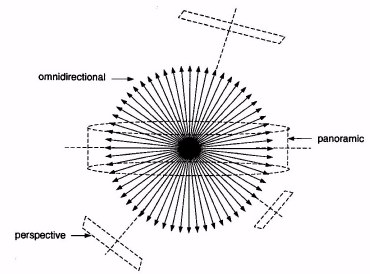
Figure1: A truly omni-directional camera views the world through an entire sphere of view as seen from its center of projection. The single viewpoint permits the construction perspective images or a panoramic image.
Traditional Imaging Systems
Most imaging systems today comprise of a photographic film camera attached to a lens. The image for most camera lenses is perspective and has a single center of projection (viewpoint). The lens typically has small field of view that corresponds to a small cone (see Figure 2a).
Figure 2: (a) A conventional imaging system and its limited field of view. (b) A larger field of view may be obtained by rotating the imaging system about its center of projection, (c) appending a fish-eye lens to the imaging system, and (d) imaging the scene through a mirror.
One way to increase the field of view is to rotate the camera about its center of projection, as shown in Figure 2b. The sequence of images can be stitched together to obtain a panoramic view of the scene. Such an approach has recently been proposed by investigators (McMillan and Bishop-1995). The disadvantages of this system are that it requires the use of moving parts and precise positioning; and it takes time to get an image with a large field of view.
If we replace the lens of a conventional camera with a fish-eye lens, that enables the camera to view objects within as much as a hemisphere (see Figure 2c). It turns out that it is difficult to design a fish-eye lens with single viewpoint (i.e. there are more than one focal point, hence the image becomes blurry). In addition, to capture a hemispherical view, the fish-eye lens must be large and hence expensive (Nayer-1997a).
Catadioptric Systems
As I mentioned earlier, when we combine a camera with a mirror, we can obtain a larger field of view (see Figure 2d). The rear-view mirror in a car is used exactly in the same fashion. The shape and position of the objects in the image depends on the type of the mirror. While it is easy to increase the field of view, it is hard to keep the effective viewpoint fixed in the space. The reason that a single viewpoint is so desirable is that it allows us to generate geometrically correct perspective images from the images captured by the catadioptric camera. Figure 3a shows a picture captured by an omni-directional camera. As you can see, it is warped and is not very hard to perceive until we generate the perspective image (figure 3b) which is not distorted anymore. These perspective images can be used for computer vision purposes. Moreover, if the image is to be presented to a human, it should be a perspective image so as not to appear distorted.
Figure 3: (a) A 360-degree image captured by an omni-directional camera, (b) The corresponding perspective image
In each catadioptric imaging system, there are two properties that affect the quality of the images.
Resolution: The resolution of a catadioptric imaging system is not, in general, the same as that of the mirror or the camera used to construct it.
Focusing: It is proved that a curved mirror increases the image blur. The finite size of the lens aperture and the curvature of the mirror are the causes of blur in a catadioptric system (Hecht and Zajac-1974).
Depending on what type of mirror is used in the system, these properties can be different from one imaging system to another. The most popular mirrors that can be used are the hyperboloid, the spheroid, and the paraboloid. Each on has its own advantages and drawbacks.
Design Constraints of a Single View Point Catadioptric Camera
As you can see in Figure 4, only paraboloid and hyperboloid mirrors have single viewpoint, while spheroid mirror has more than one. But it does not mean that the spheroid is not suitable for catadioptric systems. Spheroid mirrors typically provide images with higher resolution. One problem that all three types share is the field curvature. It means that it is difficult to focus the entire scene at the same time. Either the center of the mirror is well focused or the points around the edge are focused, but not both (Baker and Nayar-1999). We will examine the properties of all three types of mirrors in order.
Figure 4: Paraboloid, hyperboloid and spheroid mirror systems. The spheroid does not have a single view point.
A) Hyperboloid Mirrors
Hyperboloids have a single viewpoint; therefore the perspective images can be easily obtained from distorted images. But there are manufacturing difficulties with hyperboloid systems. The most obvious is the need for an aspheric mirror, which is expensive and difficult to make. Their calibration is hard, because the viewpoint of the camera must be placed at a precise location that depends on the exact shape of the hyperboloid. The good news is that as the mirror becomes smaller in size, the field curvature (defocusing) decreases and field of view increases.
B) Spheroid Mirrors
Spheroids do not have a single viewpoint. Instead, they have a good resolution at high elevations (90 degrees vertically) and that stays good until approximately horizontal. Put differently, the resolution can be approximated constant until elevation dips below horizontal, at which point it starts to fall off rapidly. This is not the case for paraboloid and hyperboloid mirrors as their resolution decreases linearly toward lower angles. Spherical mirrors have been used to construct stereo vision systems to measure the distance of objects, because multiple viewpoints are a requirement for a stereo system.
C) Paraboloid Mirrors
Paraboloid mirrors, in general, are easier to use for several reasons. First of all, they have a single viewpoint. Secondly, their calibration is far easier, because the mirror can be positioned at any distance from the camera as long as their optical axes are aligned (Nayar-1997b). A drawback of using a paraboloid is the need for a camera lens that must be as wide as the mirror, which makes it difficult to place the camera near the mirror without self-occlusion (see Figure 5).
Figure 5: A catadioptric imaging system with a parabolic mirror. Since the camera lens must be the same size of the mirror, a portion of the field of view is blocked by the camera.
Discussions and Conclusions
If we decide to work with a system that has a single viewpoint, we need to sacrifice other desirable optical parameters such as resolution. For paraboloid and hyperboloid (figures 3a and 3b), the resolution gets worse moving along the mirror toward the revolution axis. Thus, if you want to image the ground in all directions, you will get high resolution there, but poor resolution in overhead regions. For this reason, typically these devices are limited to elevation field of view of 90 degrees or less (Derrien and Konolige-2000). If we relax the single viewpoint constraint, more mirror shapes such as ellipsoid become possible. Which then is the best mirror shape to use?
Unfortunately, there is no simple answer to this question. If the application does not require a single viewpoint, and we are interested in the resolution of the images, a catadioptric system with a circular mirror (spheroid) can be used. If the application requires exact perspective projections, then hyperboloid and paraboloid are the alternatives. As far as the choice between hyperboloid and paraboloid goes, paraboloid makes the construction and calibration of the entire catadioptric system easier, as discussed earlier. Therefore, an omni-directional imaging system with a parabolic mirror is a reasonable choice for robot navigation tasks in which images with high resolution are not necessary. The implementation of such a task is an interesting topic for future studies.
Reference:
[Baker and Nayer-1999] S. Baker and S. K. Nayar. A theory of Single-Viewpoint Catadioptric Imaging Formation. International Journal of Computer Vision 35(2), 196 1999
[McMillan and Bishop-1995] L. McMillan and G. Bishop. Plenoptic Modeling: An Image-Based Rendering System. Computer Graphics: Proceedings of SIGGRAPH 95, pages 39-46, 1995
[Nalwa-1996] V. Nalwa. A True Omnidirectional Viewer. Technical Report, Bell Laboratories, Holmdel, NJ 07733, U.S.A., 1996
[Derrien and Konolige-2000] S. Derrien and K. Konolige. Approximating a Single Viewpoint in Panoramic Imaging Devices. Proceedings of the 2000 IEEE, 2000
[Nayer-1997a] S.K. Nayar. Catadioptric Omnidirectional Camera. In Proceedings of the 1997 Conference on Computer Vision and Pattern Recognition, pages 482-488, 1997
[Nayar-1997b] S.K. Nayar. Omnidirectional Video Camera. In Proceedings of the 1997 DARPA Image Understanding Workshop, 1997